Tapered size and ruggedness design, demand of vehicle locating and marine navigation GNSS antenna that will sustain harsh environment. The internal use of QUADRIFILAR Helix Antenna allows for a wider signal reception angle.
- Low noise figure
- Fully weather proof IPX7.
- Ultra-high Sensitivity
- Compact construction
- Excellent temperature stability
- Support GPS/GLONASS/BEIDOU/GALILEO and QZSS system
The antenna system MA-680D is the integration of the high performance GNSS QUADRIFILAR Helix antenna and a low noise amplifier into state-of-the-art low a very low profile/extremely compact/fully waterproof antenna signal enclosure. When connected to a GPS receiver with +3~16V DC antenna power it provide excellent signal amplification and out-band-rejection for that receiver.
Features:
GNSS antenna with double threaded bolts and through holes for cable routing with course & fine treaded pitch locking for wing-nut fastener and lock-nut to prevent vibrations and un-authorize removal.
Applications:
Geospatial Surveys / Single & Multiple frequencies RTK positioning / Vehicle Tracking / Security Surveillance / Precise Guidance / Machine Control / AVL
| PHYSICAL CONDITION |
| Constructions: |
ASA-UV radome, detachable cable/connector for easy mount, rubber-Oring between top radome and screw base for waterproof. |
| Dimensions: |
60mm(Dia.) x 90mm(H) |
| Weight: |
170grams (w/o cable & connector). |
| Color: |
Standard in ivory white |
| Mounting: |
Bulkhead mount with 0.8 inch threaded wing nut (standard accessory). |
| Cable & Connector |
| RF cable: |
SMA(M) +10 meter CFD200 +TNC(M) |
| Pulling strength: |
6 Kg @ 5sec. molded plastic on connector end for strain relief. |
| Antenna Connector |
SMA(F) or TNC(F) |
| Antenna Element |
| SUPPORT Band: |
GPS:L1/L2/L5 : GLONASS : L1/L2/L3 :BDS :B1/B2/B3
GALILEO:E1/E5/E6 & L-Band |
| Polarization: |
R.H.C.P. (Right Handed Circular Polarization). |
| peak Gain: |
≧2.5 dBi typical. |
| Gain @ 10o Elevation: |
-1 dBi typical. |
| Axial Ratio@zenith: |
≦2.0 dB |
| Azimuth coverage |
360˚ |
| Output Impedance: |
50 ohm |
| Low Noise Amplifier |
| Center Frequency: |
1164MHz~1283MHz & 1525MHz~1615MHz |
| Power Gain: |
35db +/-3db |
| Group delay variation |
≦2.0 db |
| Noise Figure: |
1.5 tpy |
| Output VSWR |
≦2.0:1 |
| Supply Voltages: |
3~16V DC. |
| Current Consumption: |
≦30mA (5V) |
| Output Impedance: |
50 ohm |
| Overall Performance: (antenna element, LNA & coax cable) |
| Center Frequency: |
1164MHz~1283MHz & 1525MHz~1615MHz |
| Gain: |
35db +/-3db |
| Noise Figure: |
2.0 max. |
| Axial Ratio: |
2 dB |
| Azimuth coverage |
360˚ |
| VSWR: |
2.0 max. |
| Output Impedance: |
50ohm |
| Environmental |
| Operating Temperature: |
-40oC~ +85oC. |
| Storage Temperature: |
-40oC~ +85oC. |
| Relative Humidity: |
95% non-condensing. |
| Water Resistance: |
100% waterproof. |
*This specification is subject to change without prior notice
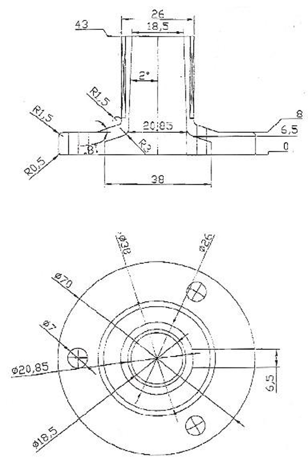
FB1 Base mounting
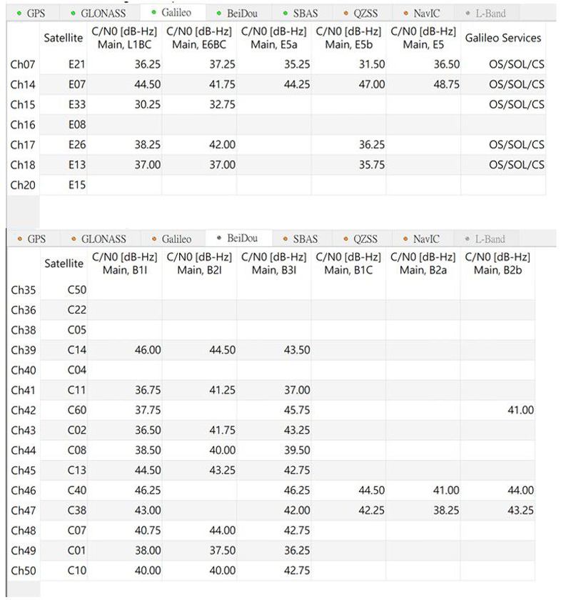
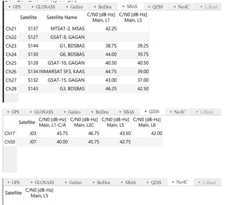
1. Antenna working frequency band
Passive antenna microwave anechoic chamber relative waveform diagram
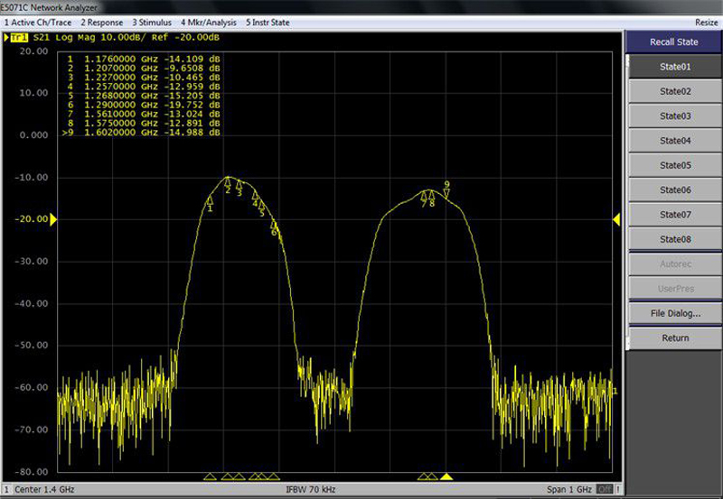
Active antenna microwave anechoic chamber relative waveform diagram
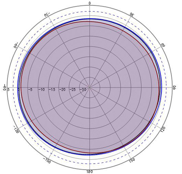
2. Antenna pattern and axial ratio Typical direction diagram of L2 vertical plane
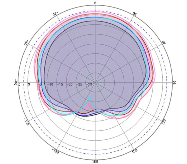
| Freq(MHz) |
Polarization |
Peak gain(dBi) |
HPBW(3dB)(deg) |
| 1176 |
RHCP |
-2.3 |
110 |
| 1192 |
RHCP |
-0.3 |
115 |
| 1207 |
RHCP |
1.5 |
117 |
| 1227 |
RHCP |
2.8 |
117 |
| 1246 |
RHCP |
1.6 |
119 |
| 1268 |
RHCP |
0 |
120 |
Passive antenna vertical plane pattern@L2
Typical direction diagram of L1 vertical plane (phi=0):
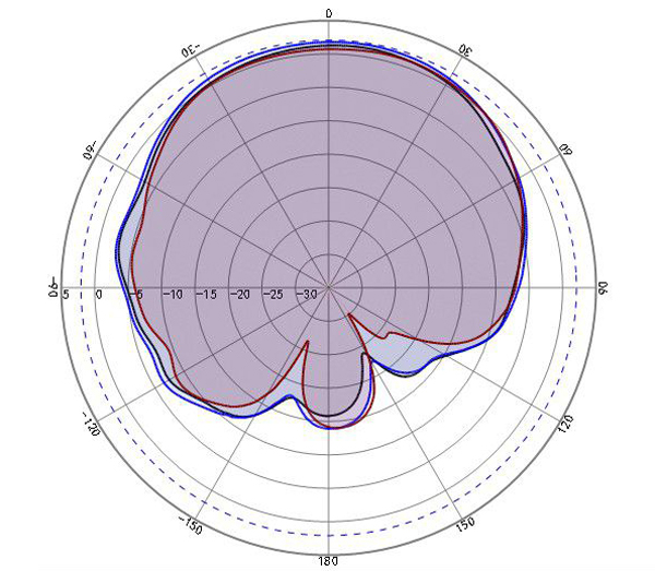
| Freq(MHz) |
Polarization |
Peak gain(dBi) |
HPBW(3dB)(deg) |
| 1561 |
RHCP |
2.3 |
96 |
| 1575 |
RHCP |
2.7 |
100 |
| 1602 |
RHCP |
2.0 |
101 |
Passive antenna L1 frequency band vertical plane pattern@L1
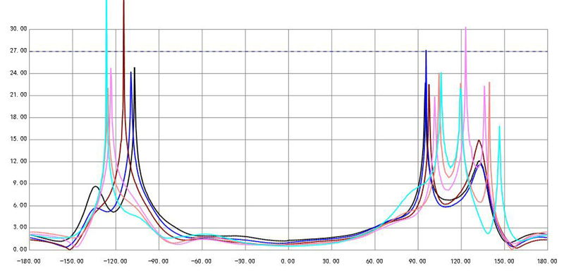
Typical direction diagram in the horizontal plane:
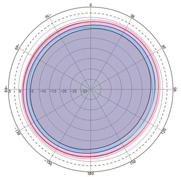
| Freq(MHz) |
Circularity(dB) |
| 1176 |
1.2 |
| 1192 |
1.1 |
| 1207 |
0.9 |
| 1227 |
0.9 |
| 1246 |
1.0 |
| 1268 |
0.8 |
Passive gain out-of-roundness@L2
| Freq(MHz) |
Circularity(dB) |
| 1561 |
0.9 |
| 1575 |
1.0 |
| 1602 |
1.2 |
Passive gain out-of-roundness@L1
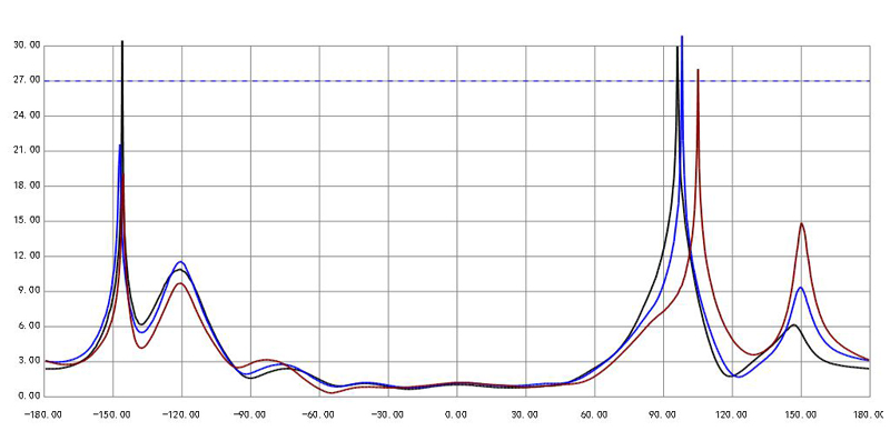
Antenna axis ratio:
| Freq(MHz) |
@Zentth(dB) |
| 1176 |
1.3 |
| 1192 |
1.0 |
| 1207 |
0.8 |
| 1227 |
0.7 |
| 1246 |
0.7 |
| 1268 |
0.6 |
Axle ratio@L2
| Freq(MHz) |
@Zentth(dB) |
| 1561 |
1.1 |
| 1575 |
1.2 |
| 1602 |
1.2 |
Axle ratio@L1
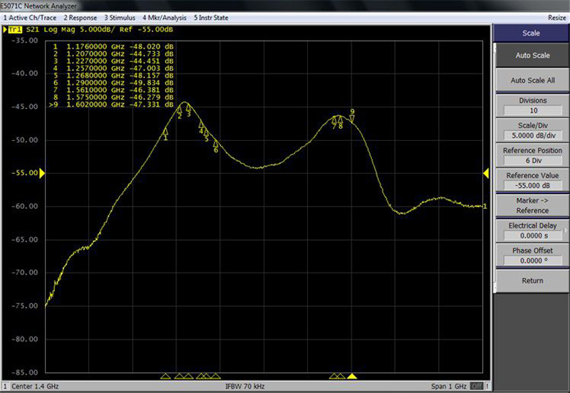
3. LNA gain and standing wave ratio
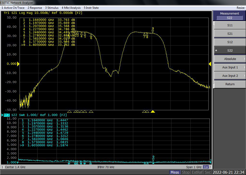
LNA gain and standing wave ratio
4. Working current
Working current is about 30mA
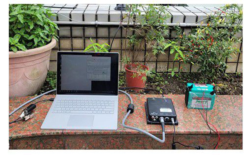
5. Test