1.1. Key Features
1.2 Power Supply
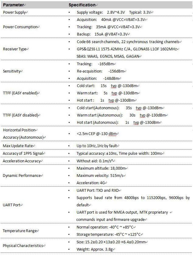
Regulated power for the RB-1513G-MTGN is required. The VCC Pin Need a stable DC voltage supply. Power supply ripple must be less than 30mV. The input voltage Vcc should be 2.8V~4.3V, Recommended power supply voltage is 3.3V. maximum current is 40mA. Suitable decoupling must be provided by external decoupling circuitry.
1.3 UART Ports
The module supports two full duplex serial channels UART. All serial connections are at 3V CMOS logic levels, if need different voltage levels, use appropriate level shifters. The baud rate of both serial ports are fully programmable, the data format is however fixed: X, N, 8, 1, i.e. X baud rate, no parity, eight data bits and one stop bit, no other data formats are supported, LSB is sent first. The modules default baud rate is set up 9600bps, however, the user can change the default baud rate to any value from 4800 bps to 115kbps. UART port can be used for firmware upgrade, NMEA output and PMTK proprietary commands input.
2 Application
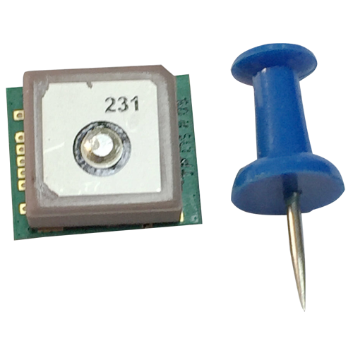
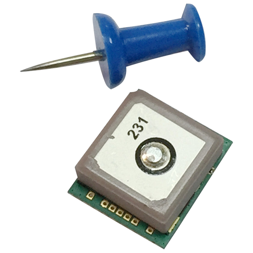
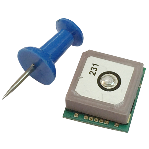
The module is equipped with a 7-pin pad that connects to your application platform. The RB-1513G-MTGN module It consists of a MediaTek MT3333 single chip GNSS IC which includes the RF part and Baseband part, a patch antenna, a LNA, a SAW filter, a TCXO, a crystal oscillator.
2.1. Pin Assignment
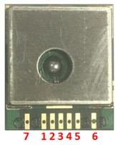
Figure 2: Pin Assignment
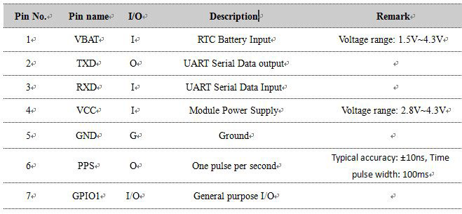
Table 2: CON Pin Description
2.2 Mechanical Dimensions
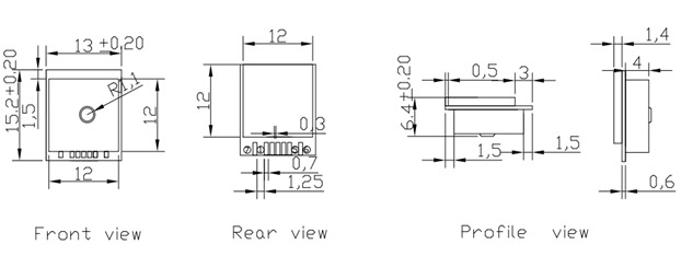
This chapter describes the mechanical dimensions of the RB-1513G-MTGN module. Size unit(mm)
3 NMEA 0183 Protocol
The NMEA protocol is an ASCII-based protocol, Records start with a $ and with carriage return/line feed. GPS&GLONASS specific messages all start with $GPxxx/$GLxxx where $GNxxx is a three-letter identifier of the message data that follows. NMEA messages have a check sum, which allows detection of corrupted data transfers.
3.1 Location mode configuration instructions
Single system or dual system positioning mode can be selected through the configuration instructions, configuration instructions such as Table 1.
Table 1: Instruction configuration instructions

- RB-1513G-MTGN initialization location mode for GPS&GLONASS dual mode.
Output data:$GNRMC. $GNGGA. $GPGSV. $GLGSV. $GPGSA. $GLGSA.$GNGLL. $GNVTG
3.2 NMEA-0183 data Detailed field
3.2.1 GGA-Global Positioning System Fixed Data
$xxGGA, 161229.487,3723.2475,N, 12158.3416,W, 1,07,1.0,9.0,M.0000*18
Table 2: GGA Data Format
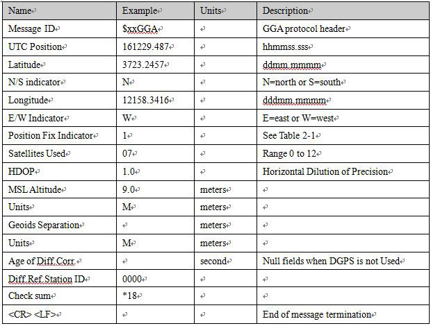
Table 2-1: Position Fix Indicators

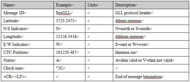
3.2.2 GLL-Geographic Position – Latitude/Longitude
$xxGLL , 3723.2475, N,12158.3416, W,161229.487, A*2C.
Table 3: GLL Data Format
3.2.3 GSA-GNSS DOP and Active Satellites
$xxGSA , A, 3, 07, 02, 26,27, 09, 04,15, , , , , , 1.8,1.0,1.5*33.
Table 4: GSA Data Format
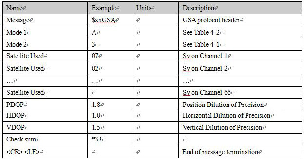
Table 4-1: Mode 1

Table 4-2: Mode 2

3.2.4 GSV-GNSS Satellites in View
$xxGSV , 2, 1, 07, 07, 79,048, 42, 02, 51,062, 43, 26, 36,256, 42, 27, 27, 138,42*71
$xxGSV, 2, 2, 07, 09, 23,313, 42, 04, 19, 159, 41, 15,12,041, 42*41.
Table 5: GSV Data Format
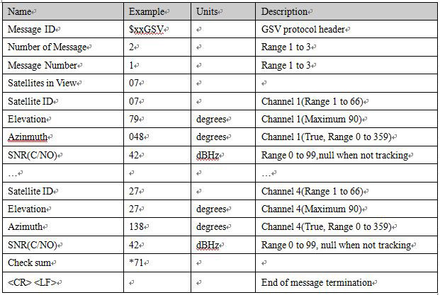
- Depending on the number of satellites tracked multiple messages of GSV data may be required.
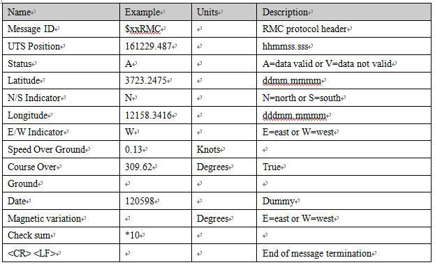
3.2.5 RMC-Recommended Minimum Specific GNSS Data
$xxRMC, 161229.487, A, 3723.2475, N, 12158.3416, W, 0.13,309.62, 120598,, *10
Table 6: RMC Data Format
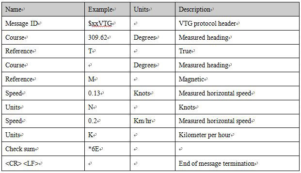
3.2.6 VTG-Course Over Ground and Ground Speed
$xxVTG, 309.62, T, M, 0.13, N, 0.2, K*6E
Table 17: VTG Data Format
